2026 Top Rotary Valves How to Choose the Right Type?
Choosing among the 2026 top rotary valves is not simply a matter of comparing catalog ratings. The right choice depends on what the valve must handle, how often it operates, and what the surrounding process can support. A model that performs well with dry, free-flowing granules may struggle with sticky powder or fragile pellets. Small details matter.
Start with the material. Note its particle size, abrasiveness, moisture, temperature, and tendency to bridge or compact. Then consider throughput, pressure difference, required metering accuracy, and available space. These conditions help narrow the field to airlock, metering, diverter, or other rotary valve designs. They also reveal when a standard configuration may be a poor fit.
Construction deserves equal attention. Housing and rotor materials, clearances, seal design, drive arrangement, and access for cleaning can affect service life and maintenance time. For example, a dusty application may need effective shaft sealing, while abrasive solids can accelerate wear around rotor tips. Check manufacturer data against the actual operating conditions, not just ideal test figures. Ask for relevant application references or technical support when the consequences of a mismatch are significant.
There is no universal winner. Even a well-specified valve can disappoint if installation, upstream feeding, or maintenance is overlooked. That part is easy to underestimate. This guide compares key rotary valves and explains how to match their features to real process needs. Use it as a practical starting point, then confirm final sizing and configuration with qualified engineering advice. A little uncertainty is healthy; process data is often less complete than a selection chart suggests.
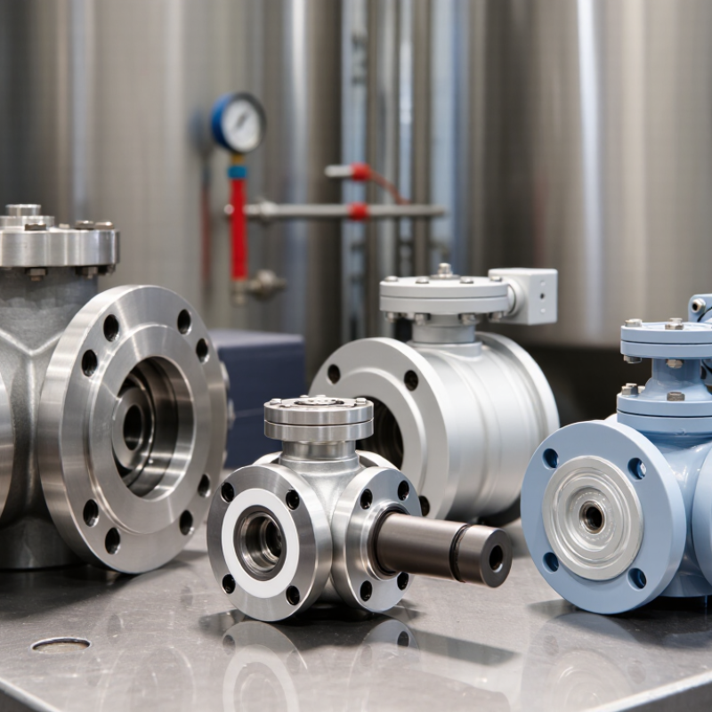
Rotary Valve Types Explained: Drop-Through, Blow-Through, and Feeder Designs
Rotary valves transfer powders and granules while helping maintain a controlled material flow. The right design depends on where the valve sits and what the process needs. Small differences matter. Particle size, temperature, pressure, and the risk of product damage all affect the choice.
A drop-through valve lets material fall by gravity through the rotor pockets. It suits applications such as discharging from a hopper into a lower bin, where the route is direct and gentle. A blow-through valve places a conveying line beneath the rotor. Air carries each pocket’s contents downstream, making this design useful for pneumatic transport. It can also create more wear, especially with abrasive particles. Check clearances and inspect the rotor regularly.
Feeder designs focus on metering material at a steady rate, rather than simply passing it onward. They are common beneath storage vessels feeding mixers or process lines. In practice, though, a feeder’s accuracy can shift with material density, moisture, and hopper flow. Test with the actual product when possible. A valve that works neatly with dry pellets may behave quite differently with a fine, cohesive powder.
Characterize the Solids: Particle Size, Bulk Density, Moisture, and Abrasiveness
2026 Top Rotary Valves How to Choose the Right Type?
Start with a representative solids sample, not a convenient handful from the surface.
Particle size distribution matters: coarse granules may feed predictably, while fine powder can leak through clearances or become airborne. Look for fines, flakes, and occasional oversized pieces. They can change how rotor pockets fill.
Bulk density also affects capacity calculations; a light, fluffy powder behaves differently from dense pellets at the same volume. Measure it under conditions that reflect actual handling. Small details matter.
Moisture can turn free-flowing material into clumps that bridge above the valve or smear across internal surfaces. Check samples after storage and during humid periods, not only when they seem dry. That test is easy to overlook.
Abrasive solids, such as gritty mineral powders, can gradually wear rotor tips and housing surfaces. Ask how much wear is acceptable between inspections, and consider suitable contact materials and clearances. There is no universal setting: tighter clearances may reduce leakage but can increase sensitivity to particles or temperature changes. Record what the material actually does during feeding, then confirm valve performance under realistic operating conditions.
Estimate Capacity: Output = Displacement per Revolution × RPM × Fill Efficiency
2026 Top Rotary Valves: How to Choose the Right Type?
Estimate capacity with a practical starting point:
output = displacement per revolution × RPM × fill efficiency.
If a valve moves 0.8 liters per revolution, runs at 20 RPM, and achieves 75% fill efficiency, estimated output is 12 liters per minute. Keep units consistent. A displacement stated in cubic meters must be converted before comparing it with a target in liters per hour.
The calculation is an estimate, not a guarantee. Powder shape, moisture, particle size, and inlet flow can all change how fully each pocket fills. Watch the material enter the valve. Does it form a steady curtain, or bridge above the inlet? That detail matters.
A speed increase may raise theoretical capacity, but it can also reduce filling time or increase wear. Check the required throughput at the actual operating conditions, then compare it with measured performance where possible. I would leave a reasonable margin; the right amount depends on how variable the material is. Even a tidy spreadsheet can miss a stubborn, clumping powder.
Check Pressure and Temperature Ratings: 1 bar (15 psi) Is a Common Airlock Benchmark
For rotary valves, “1 bar (15 psi)” is a useful airlock benchmark, not a universal rating. One bar equals 14.5 psi, but confirm whether a datasheet means gauge pressure or absolute pressure. More importantly, check the maximum differential pressure across the rotor, housing, seals, and end plates. A valve may handle ordinary conveying conditions yet leak or wear quickly under repeated pressure cycling. Small detail, big consequences.
Temperature matters just as much. Compare the process temperature with the limits for seals, bearings, and rotor clearances, including heat from cleaning or nearby equipment. The U.S. Department of Energy’s Improving Compressed Air System Performance guide reports that leaks can waste 20–30% of compressor output in typical industrial systems. It is not a rotary-valve rating study, but it shows why leakage deserves attention. Ask suppliers for test conditions, not just a headline pressure figure. Then compare those conditions with your actual duty: product bulk density, abrasiveness, and starts per hour. A brief pressure spike can matter. I would also leave a margin; real plants rarely behave like tidy datasheets.
Rotary Valve Pressure Reference: Bar to PSI
One bar equals approximately 14.5 psi, making 1 bar a useful reference point when reviewing airlock pressure requirements. These bars show unit conversions, not rotary valve ratings. Always check the selected valve’s specified pressure and temperature limits for your application.
Select Materials and Safety Features: Stainless Steel, ATEX, and NFPA 69 Considerations
Choosing a rotary valve starts with the material, not just the flow rate. Stainless steel can suit corrosive products or washdown areas, but grade, surface finish, and seal compatibility matter. A polished housing may look reassuring; it does not guarantee that every internal surface is easy to clean. Check the actual powder or granule, operating temperature, and cleaning routine.
For combustible dust, assess the complete installation against the applicable ATEX requirements. The valve alone does not make a system safe. Review ignition sources, grounding, isolation, and how the equipment connects to the rest of the process. NFPA 69 guidance may also inform explosion prevention and protection measures, depending on the site and jurisdiction. Ask qualified safety professionals to verify the design and documentation.
Details count. A fine, dry powder can leak through clearances that work well for coarse pellets. Specify the expected particle size, pressure difference, and duty cycle, then confirm them with the supplier’s technical data. I have seen selection discussions focus heavily on stainless steel while overlooking seals and inspection access. That deserves a second look.