Solar growth makes rail selection more than a detail on a purchasing list. IRENA’s Renewable Capacity Statistics 2024 reports that global solar capacity grew by about 346 gigawatts in 2023. That scale puts practical pressure on every part of a mounting system. Fatih Birol, executive director of the International Energy Agency, described solar PV as “the new king of the world’s electricity markets.” His observation captures the momentum, but not the installation challenge. Every roof is different.
Aluminum Solar Rails must suit the modules, roof type, span, and expected wind and snow loads. Check the alloy and temper, profile dimensions, connector compatibility, and corrosion protection. Then review the manufacturer’s load tables and installation instructions; a thick-looking rail is not proof of adequate capacity. Small details matter. A splice placed between supports, for example, can change how a rail behaves under load. A rail that works well on one roof may not suit another, and that is easy to overlook when comparing prices alone. IRENA’s figures describe market growth, not product performance, so they cannot replace project-specific engineering checks. The right choice balances verified structural data, installation practicality, and long-term durability. It may take an extra calculation. Worth doing.
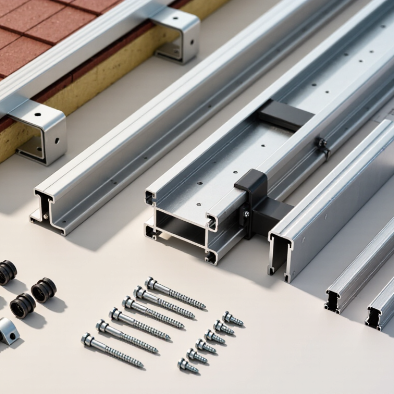
Aluminum solar rails are the structural tracks that connect roof attachments to solar panels. They give installers a straight, stable path for positioning modules and securing them with clamps. Without rails, panel edges can sit unevenly, and loads may not transfer as intended to the roof structure.
A rail system usually includes aluminum profiles, panel clamps, and brackets or feet fixed to suitable roof attachment points. The brackets carry forces from wind and snow into the building, while the rails spread support along the panel row. Check that the rail dimensions and clamp positions match the module specifications. Small details matter. A few millimeters can affect fit.
Aluminum is relatively light and resists corrosion, which helps on exposed rooftops. But it still needs compatible fasteners and careful installation; dissimilar metals or trapped moisture can cause problems over time. Rails also expand and contract with temperature, so installers should follow the system’s spacing and joint guidance. Measure the roof, inspect the mounting surface, and confirm local wind and snow conditions before choosing a layout. A rail that looks sturdy on the ground may behave differently on a sloped, uneven roof. That part is easy to underestimate.
What aluminum solar rails are and how they support solar panels
Solar rails support panels and transfer their loads to the mounting points on a roof or ground structure. Common aluminum alloys used for extruded components, such as 6063 and 6061, have a density of about 2.70 g/cm³, compared with about 7.85 g/cm³ for carbon steel. These are typical material values; density alone does not determine a rail’s strength or safe span. Choose rails using the system’s engineering specifications, including profile, alloy and temper, support spacing, and local wind and snow loads.
Rail selection starts with the roof, not the module. On asphalt shingles, flashed attachments should reach sound rafters; missed framing can create leaks. Standing-seam metal roofs may use seam clamps, but the seam profile and clamp compatibility must be verified. Tile roofs need careful load paths and access for replacing cracked tiles. Small details matter.
Then check the site. Snow accumulation, wind exposure, roof age, and salt in coastal air all affect rail spacing, attachment choice, and corrosion resistance. NOAA’s 1991–2020 U.S. Climate Normals provide station-level snowfall and wind data for initial screening. They do not replace structural calculations using locally applicable design loads. NREL’s 2023 Q1 U.S. Solar Photovoltaic System and Energy Storage Cost Benchmarks models an 8-kWdc residential rooftop system; useful cost context, but not a roof-specific rail design.
Before choosing rails, confirm rafter locations, roof condition, and the clearances needed around vents or valleys. A site drawing can look tidy and still miss an uneven roof plane. That is worth checking twice. Aluminum rails may suit many roofs, but rail span and attachment spacing must match the loads and mounting system. A lighter layout is not automatically a safer one.
Choosing aluminum solar rails starts with the loads they must carry, not with appearance alone. A rail supporting modules across a long span may need a taller profile or closer support spacing than one with short spans. Check the module layout, rail orientation, and approved clamp zones together. Small details matter.
Account for module weight, mounting hardware, and site-specific wind and snow loads. Wind uplift can pull on fasteners, while accumulated snow adds downward force. Both affect the rail and its connections. Use the project’s load calculations and the rail supplier’s span tables; do not assume two rails with similar dimensions have equal capacity. Alloy, temper, wall thickness, and cross-section all influence performance.
Deflection deserves attention, too. A rail can resist failure yet bend enough to stress module frames or loosen connections. Compare the proposed span with allowable deflection limits, and verify fastener spacing and attachment points. Measure twice. It is tempting to choose a heavier rail for reassurance, but that may add cost without fixing poor support placement. I would recheck assumptions when roof exposure, terrain, or snow conditions are uncertain, and ask a qualified professional to review the design.
Before selecting aluminum solar rails, compare the rail interface with the mount hardware and the module frame. Check the module installation manual for approved clamp zones, frame thickness, and edge-clearance requirements. Then confirm that the mount’s bolts or sliding nuts fit the rail channel. A clamp that tightens smoothly may still sit outside the approved zone. Small mismatch, real risk.
Use drawings, not appearance alone. Measure the module frame and rail slot, and check the mount’s specified fasteners and torque. Verify that the complete assembly provides the required bonding path; UL 2703 covers testing for mounting systems, bonding, and grounding. For site loads, have a qualified designer check the rail span, attachment points, and wind and snow assumptions. Compatibility is system-specific.
The scale of the market makes careful checking practical: IEA PVPS reported about 1.6 terawatts of cumulative global PV capacity by the end of 2023 in its Trends in Photovoltaic Applications 2024 report. That figure does not establish a universal rail standard. Module frames and mounting details still vary. Keep the module manual and mount documentation together, and confirm any unclear clamp limits with the manufacturer before installation. A neat fit is not proof.
| Compatibility Check | What to Measure or Confirm | Typical Information | How to Verify the Fit |
|---|---|---|---|
| Solar module frame thickness | Measure the module frame height where the clamps will grip it. | Framed modules are commonly offered with frame heights such as 30 mm, 35 mm, or 40 mm; dimensions vary by module model. | Choose mid clamps and end clamps whose stated frame-height range includes the measured module frame. |
| Clamp-to-rail interface | Check the clamp fastener, rail channel opening, and the shape and dimensions of the rail slot. | Rail profiles and T-bolt or channel-nut dimensions are system-specific; there is no single universal rail-slot size. | Confirm that the clamp fastener is designed for the exact rail profile. Do not assume that a bolt fits because its diameter appears suitable. |
| Module clamp zones | Find the module manufacturer’s permitted clamping zones and the required clamp contact area. | Permitted zones depend on the module construction and installation orientation. They are normally specified in the module installation instructions. | Position rails and clamps within the stated zones; do not clamp over the glass or outside the approved frame area. |
| Mount or roof-foot connection | Check how the roof mount attaches to the rail, including its fastener type, slot, and allowable adjustment. | Mount-to-rail connections differ among rail profiles and mounting systems. | Verify the mount is approved for the selected rail and that the fastener can be fully engaged and tightened as specified. |
| Rail length and module layout | Calculate rail runs from the module dimensions, clamp positions, end clearances, and array layout. | Required rail length depends on module orientation, row arrangement, clamp locations, and the selected mounting system. | Lay out the modules and clamp points before cutting rails. Follow the rail instructions for cut locations and end clearances. |
| Rail splice connection | Check the splice type, compatible rail profile, fasteners, and specified joint position. | Splices are designed for particular rail profiles. Joint placement and any required gaps or thermal movement allowances vary by system. | Use a splice specified for the rail and follow its instructions for positioning, fastening, and expansion allowance. |
| Rail span and structural capacity | Confirm support spacing, rail loading limits, roof conditions, and site-specific wind and snow loads. | There is no universally suitable support spacing; allowable spans depend on the rail profile, loads, and mounting configuration. | Use the rail system’s load tables or an approved design. Do not select rail spacing based only on module dimensions. |
| Material and installation environment | Check rail material, fastener material, coating, and exposure conditions. | Aluminum rails are commonly used in solar mounting, but compatible fasteners and corrosion considerations depend on the installation environment. | Follow the system guidance for fastener materials and avoid unapproved material combinations, especially in corrosive environments. |
| Important: Compatibility is determined by the exact rail, mount, clamp, and module models—not by appearance alone. Check the current installation instructions and structural requirements for every component before installation. | |||
Corrosion resistance starts with the site, not the brochure. Salt spray, trapped moisture, and contact with dissimilar metals can damage rails and fasteners. ISO 9223 classifies atmospheric corrosivity, helping buyers describe exposure more precisely than “coastal” or “inland.” Ask for the rail alloy, temper, coating type, and coating thickness. ASTM B117 salt-spray results can support comparisons, but they do not directly predict years of outdoor service. A long test is not a lifetime guarantee.
Standards matter at system level. Where applicable, check whether the complete mounting assembly has been evaluated to UL 2703, and confirm that the rail and fasteners match the tested configuration. IEA PVPS’s Trends in Photovoltaic Applications 2024 reports more than 400 GW of new solar capacity added worldwide in 2023. At that scale, small design choices affect long-term maintenance. Compare delivered cost per installed kilowatt, including clamps, splice plates, freight, and replacement access—not rail price alone. The cheapest option can become expensive. I still double-check fastener compatibility; it is easy to overlook.
Tips: Request coating and corrosion-test reports, then compare identical test conditions. Check drainage at rail joints, and avoid designs that leave water sitting around bolts. For harsh sites, ask for documented performance in a similar environment.
1272 Speers Rd Unit 4
Oakville ON Canada L6L 2X4
©Copyright 2020 Gosco Valves. All rights reserved.