What Is an Air Circuit Breaker?
An Air Circuit Breaker, or ACB, is a low-voltage switching device that protects electrical systems from dangerous current. It uses atmospheric air to extinguish the arc created when contacts separate. Unlike a household breaker, an ACB often serves large switchboards, industrial plants, data centers, and commercial buildings.
Inside the breaker, heavy copper contacts carry normal load current. During a short circuit, the trip unit detects abnormal current and releases the mechanism. The contacts open rapidly. Arc chutes then divide, cool, and control the electrical arc before it disappears. It happens in milliseconds. That speed protects cables, busbars, transformers, and connected equipment.
Power-system protection specialist Stanley H. Horowitz has expressed the central principle this way: “A protective device must clear a fault selectively, quickly, and reliably.” An ACB applies that principle through adjustable long-time, short-time, instantaneous, and ground-fault settings. These settings require careful coordination with upstream and downstream devices.
That explanation is useful, but incomplete. An ACB is not simply a large on-off switch. Its frame size, interrupting capacity, trip curve, and maintenance condition all matter. Dust, worn contacts, weak springs, or incorrect settings can reduce protection. A clean panel does not guarantee a healthy breaker.
In practice, technicians inspect connection torque, insulation condition, contact wear, and trip performance. They also review fault records after serious events. The best choice depends on the installation, not only the rated current. This is where design judgment matters. Mistakes can be expensive.
An air circuit breaker (ACB) is a mechanical switching device that protects electrical circuits from dangerous current. It uses ordinary air to extinguish the arc formed when its contacts separate. Unlike a simple switch, an ACB can interrupt overloads, short circuits, and certain ground faults. Its trip unit detects abnormal current and commands the mechanism to open.
The main purpose of an ACB is reliable protection in high-current, low-voltage distribution systems. It often controls incoming power, bus sections, generators, or large feeders. During normal operation, it carries substantial current with minimal resistance. During a fault, it opens rapidly and limits damage to cables, panels, and connected equipment. Adjustable trip settings help technicians coordinate protection between upstream and downstream devices.
A cabinet may show clear contact positions. That detail matters. Many ACBs also include undervoltage, shunt-trip, or remote-control functions. In field maintenance, technicians inspect contact wear, arc chutes, insulation, and closing mechanisms. Dust, loose connections, and poor lubrication can delay operation. The air medium is simple, but the interrupting process is not. A common mistake is treating the breaker as maintenance-free. It still requires testing, correct settings, and isolation procedures performed by qualified personnel. The definition sounds straightforward; real protection depends on installation quality and careful verification.
What Is an Air Circuit Breaker?
An air circuit breaker uses atmospheric air to extinguish an electrical arc. Its internal structure is arranged around current flow, arc control, and rapid tripping. The main contacts carry normal load current, while separate arcing contacts absorb most switching stress. Arc runners guide the arc into arc chutes, where metal plates divide, cool, and lengthen it.
The operating mechanism usually contains a charged spring, closing coil, opening coil, and mechanical latch. When a fault occurs, the trip unit releases the latch and opens the contacts. Electronic trip units measure current through internal sensors or current transformers. They can respond to overloads, short circuits, and ground faults. Terminal pads connect the breaker to busbars or cables. Insulating barriers keep energized sections separated.
A frame supports these parts and maintains alignment during repeated operations. In drawout designs, guide rails, shutters, and position interlocks add another protection layer. Small details matter. During maintenance, technicians often check contact pitting, loose connections, worn springs, and dust inside the arc chamber. A clean exterior proves little. Internal damage may remain hidden.
One point deserves reflection: simplified diagrams can make the mechanism look perfectly balanced. Real equipment may show uneven wear, slight contact discoloration, or delayed movement. Those signs should not be dismissed without testing. Follow the manufacturer’s technical data, isolate the circuit correctly, and verify the breaker’s condition with suitable instruments.
| Component or Structure | Primary Function | Internal Construction | Typical Materials | Operating Principle | Maintenance Focus |
|---|---|---|---|---|---|
| Insulated Frame | Supports and encloses the internal operating parts while providing electrical insulation. | Molded housing with mounting points, internal partitions, covers, and access panels. | Glass-fiber-reinforced thermoset or thermoplastic insulating material; steel hardware. | Keeps energized parts separated from the enclosure and maintains mechanical alignment. | Check for cracks, deformation, contamination, and loose fasteners. |
| Main Contacts | Carry the normal load current when the breaker is closed. | Fixed and moving contact assemblies connected to the line and load conductors. | Copper alloys with silver-based contact surfaces or other erosion-resistant contact materials. | Contacts press together to form a low-resistance current path and separate to interrupt current. | Inspect contact wear, alignment, pressure, overheating, and contact resistance. |
| Arcing Contacts | Protect the main contacts from damage caused by electrical arcing during opening and closing. | Separate contact tips positioned so they open after the main contacts and close before them. | Copper alloys and arc-resistant contact materials. | They carry the arc for a short period, allowing the main contacts to remain relatively protected. | Measure erosion and replace contacts when the manufacturer-defined wear limit is reached. |
| Arc Chutes | Extinguish and cool the arc produced when the contacts interrupt current. | Stacked insulating plates with splitter sections and arc-running surfaces located above or around the contacts. | Heat-resistant insulating plates, steel supports, and arc-resistant composites. | The magnetic field drives the arc into the chute, where it is divided, cooled, lengthened, and deionized. | Remove dust and inspect for cracked, burned, or missing plates. |
| Electronic Trip Unit | Detects abnormal current conditions and commands the breaker to trip. | Microprocessor-based sensing and control circuit with adjustable protection settings and a trip actuator interface. | Printed circuit board, electronic sensors, insulating enclosure, and low-voltage wiring. | Processes current signals and trips for overload, short circuit, and sometimes ground-fault conditions. | Verify settings, wiring, self-test results, and trip performance. |
| Current Sensors | Provide current measurements to the electronic trip unit. | One sensing element is installed around or in series with each phase conductor; an additional sensor may be used for neutral protection. | Magnetic cores, copper windings, electronic Hall-effect sensors, or integrated current transformers. | Converts primary current into a proportional electrical signal for protection and metering. | Check connections, insulation, sensor alignment, and measurement accuracy. |
| Operating Mechanism | Stores and releases mechanical energy to close or open the contacts quickly. | Linkages, shafts, cams, latches, springs, and a mechanism frame connected to the moving contact assembly. | Hardened steel shafts, alloy-steel springs, bearings, and reinforced insulating links. | A stored-energy mechanism provides rapid contact movement independent of the operator's speed. | Lubricate only specified points and inspect springs, latches, shafts, and linkages. |
| Closing Spring | Stores energy required to close the breaker. | Coil spring or torsion spring connected to a charging mechanism and closing latch. | Tempered spring steel with steel retaining components. | Energy is stored manually or by a motor and released when the closing command is received. | Check charging operation, spring condition, and charged/discharged indication. |
| Spring-Charging Motor | Automatically charges the closing spring in electrically operated breakers. | Compact motor, reduction gears, limit switch, and linkage connected to the spring-charging shaft. | Insulated motor housing, copper windings, steel gears, and molded components. | The motor runs until a limit switch detects that the spring is fully charged. | Test motor voltage, charging time, limit-switch operation, and gear condition. |
| Closing Coil | Releases the closing latch when a remote or local close command is received. | Electromagnetic coil with plunger, return spring, and mechanical linkage. | Copper coil, laminated magnetic steel, insulating bobbin, and steel plunger. | Energization moves the plunger, releases the charged mechanism, and closes the contacts. | Check control voltage, coil resistance, plunger movement, and command circuit wiring. |
| Shunt-Trip Coil | Opens the breaker when an external trip signal is applied. | Electromagnetic trip coil connected to an opening latch or trip linkage. | Copper coil, magnetic steel core, insulating bobbin, and steel actuator. | The energized coil releases the trip latch, allowing the stored opening energy to separate the contacts. | Test trip command, control voltage, coil resistance, and mechanical release. |
| Undervoltage Release | Prevents closing or initiates opening when its control voltage falls below an acceptable level. | Voltage-sensing electromagnetic device connected to the closing and tripping interlock system. | Copper coil, magnetic steel parts, spring mechanism, and insulating components. | A maintained control voltage holds the release in the permissive position; loss of voltage removes the permission. | Verify pickup, dropout, time delay if fitted, and control-circuit continuity. |
| Trip Latch and Reset Mechanism | Maintains the breaker in the closed position and releases it during a trip event. | Mechanical latch, trip bar, reset lever, springs, and position indicators. | Hardened steel, alloy components, low-friction bushings, and insulating linkages. | A trip signal disengages the latch, allowing the opening mechanism to operate and preventing unsafe reclosing. | Check free movement, latch engagement, reset action, and signs of wear. |
| Line and Load Terminals | Connect the breaker to the upstream supply and downstream circuit conductors. | Rigid terminals, pads, or plug-in primary disconnects connected to the main current path. | Tinned or plated copper, aluminum where specified, and steel mounting hardware. | Provides a low-resistance and mechanically secure connection for high current. | Inspect torque, discoloration, oxidation, insulation clearance, and temperature rise. |
| Insulation Barriers and Phase Separators | Maintain electrical clearance and prevent flashover between phases and to ground. | Barriers positioned between poles, around terminals, and near the contact and arc-chute areas. | Glass-fiber-reinforced insulating material, molded resin, or heat-resistant polymer. | Increases creepage and clearance distances and contains arc products during interruption. | Inspect for carbon tracking, cracking, moisture, and missing barriers. |
| Auxiliary Contacts | Provide breaker status signals for control, indication, interlocking, and monitoring circuits. | Small mechanically operated contact blocks linked to the main mechanism. | Silver-plated contact alloy, copper terminals, molded insulating body, and spring mechanisms. | Contact states change according to whether the breaker is open, closed, or tripped. | Test continuity in each position and inspect terminal tightness. |
| Draw-Out Cradle and Primary Disconnects | Allow the breaker to be connected, isolated, tested, or removed without disconnecting fixed conductors. | Stationary cradle with guide rails, racking mechanism, shutters, position indicators, and plug-in disconnect fingers. | Steel frame, copper disconnect contacts, insulating shutters, and mechanical interlocks. | Racking movement changes the breaker between connected, test, and disconnected positions. | Inspect alignment, racking threads, shutters, disconnect contact pressure, and position interlocks. |
| Mechanical and Electrical Interlocks | Prevent unsafe operations such as closing in an incorrect position or opening an access door while energized. | Locks, cams, levers, solenoids, auxiliary switches, and position-dependent control logic. | Steel mechanisms, molded insulating parts, and copper electrical contacts. | Blocks selected actions unless predefined mechanical position and electrical conditions are satisfied. | Test every permitted and prohibited operating sequence during scheduled maintenance. |
| Note: Exact construction, protection functions, accessory options, interrupting ratings, and maintenance intervals vary by breaker design and system application. Always use the applicable technical documentation and safety procedures for inspection or service. | |||||
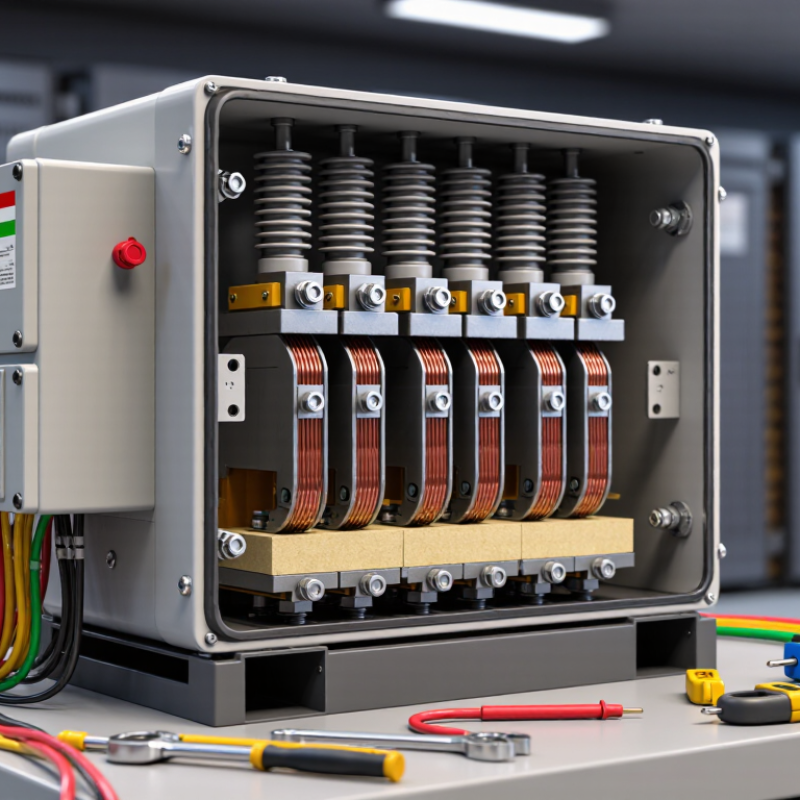
An air circuit breaker interrupts current by opening contacts inside atmospheric air. Under normal load, current travels through closed main contacts. During a fault, the trip unit detects excessive current and releases the operating mechanism. The contacts separate rapidly. An electric arc forms between them.
The arc is the difficult part. It can reach thousands of degrees Celsius and continue carrying current after contact separation. Arc runners stretch and move it into an arc chute. Inside the chute, metal plates divide, cool, and lengthen the arc. When the alternating current reaches its natural zero point, the breaker must restore insulation strength quickly. Otherwise, the arc may strike again. IEC 60947-2 establishes test requirements for low-voltage circuit breakers, including short-circuit performance and withstand verification.
Industry ratings show why this process matters. Common air circuit breakers cover continuous currents from about 630 A to 6,300 A, while short-circuit interruption ratings often range from 42 kA to 100 kA, depending on the design. These figures must be checked against the installation study. The International Energy Agency’s Electricity 2024 report also notes that data-centre electricity demand is rising sharply, increasing pressure on dependable distribution equipment. A practical weakness remains: selecting only by normal load can miss the fault duty. Engineers should review prospective short-circuit current, clearing time, temperature, and maintenance records together. The arc is brief, but never harmless.
What Is an Air Circuit Breaker? Types and Operating Characteristics
An air circuit breaker (ACB) protects low-voltage systems by interrupting current through air. It commonly serves large panels, generators, and industrial distribution boards. The arc travels through an arc chamber, where splitter plates cool and divide it. A stored-energy spring mechanism opens the contacts quickly. That speed matters. IEC 60947-2 defines key requirements for rated current, short-circuit performance, and temperature rise.
ACBs generally use thermal-magnetic or electronic trip units. Thermal protection responds to prolonged overloads, while magnetic protection reacts to severe short circuits. Electronic units offer adjustable long-time, short-time, instantaneous, and earth-fault functions. Fixed ACBs suit stable installations. Withdrawable versions allow safer inspection and faster replacement. Typical frame ratings can reach 6,300 amperes, although the correct value depends on the installation design. Selective coordination also matters. A downstream breaker should operate before the upstream ACB, limiting unnecessary outages.
Global electricity demand grew by about 2.2% in 2023, according to the International Energy Agency’s Electricity 2024 report. Ember’s Global Electricity Review 2024 recorded a similar increase and noted that clean power supplied 30% of global electricity. More connected loads may increase the need for dependable distribution protection. Still, higher capacity does not automatically mean better protection. Incorrect trip settings can delay fault clearance or create nuisance trips. Field testing should confirm contact resistance, insulation condition, trip timing, and mechanical operation. I have seen calculations look perfect on paper. Real panels can be dirtier, hotter, and less predictable.
An air circuit breaker (ACB) is a low-voltage switching and protection device that uses air to extinguish the electrical arc. Fixed, draw-out, and current-limiting ACBs are commonly selected according to installation requirements, maintenance access, and fault-level protection.
The chart shows representative operating times for common ACB protection functions. Instantaneous protection clears severe short circuits fastest, while short-time and long-time protection provide coordination with downstream devices. Actual values depend on the trip-unit settings, rated current, system fault level, and applicable standards.
What Is an Air Circuit Breaker?
Air circuit breakers (ACBs) protect low-voltage power systems by interrupting faults in air. They are common in main switchboards, generators, factories, and data centers. Their adjustable trip settings support selective coordination, helping isolate one faulty feeder instead of shutting down an entire facility. Drawout designs also make testing and isolation more practical.
Demand is rising. The International Energy Agency’s Electricity 2024 report forecasts average global electricity-demand growth of 3.4% annually from 2024 to 2026. Larger electrical loads increase the value of dependable protection. However, an ACB is not a magic shield. Its performance depends on correct short-circuit ratings, suitable settings, and proper installation. A poorly adjusted breaker can trip too late or interrupt healthy equipment.
Maintenance needs are specific. Inspect contact wear, arc chutes, terminals, insulation, springs, and trip units. Remove dust carefully. Verify mechanical operation and electrical protection through documented testing. NFPA 70B’s 2023 edition emphasizes a formal electrical-equipment maintenance program, including defined intervals and records. Actual intervals should follow operating conditions, fault exposure, and manufacturer instructions.
Tips: Keep a clean maintenance log. Test after major faults. Do not rely only on visual checks. Field conditions often expose weaknesses that commissioning tests miss.
One detail deserves reflection: preventive maintenance costs time, but unexpected downtime usually costs more. In critical systems, that trade-off should be calculated, not assumed.
1272 Speers Rd Unit 4
Oakville ON Canada L6L 2X4
©Copyright 2020 Gosco Valves. All rights reserved.